3D animation tutorials

More on bump maps

When to use bump maps.

This was made with Maya and rendered with mental ray.

The stone walls have a heavy bump map.  The material was made with a tileable stone texture and the bump map was made from the same seamless texture.

The bed was sculpted with the Maya sculpting tool found in Modeling under Surfaces.  The bedspread material is made from a seamless cloth texture and the bump map for it was made from the same seamless texture.

The cement floor was made from a seamless cement texture and again, the same texture was used to make a bump map.

The sink/toilet combo and the metal bars were made with mental ray “paint” materials.  Since they are smooth and shiny, they are not bump mapped.

This images can be clicked on to blow them up.

Here are two variations:

3D animation tutorials

More on bump maps

Bump maps on plaster, metal, stone, and mortar.

The image below was made in Maya and rendered with mental ray.  The plants inside the building were made with PlantFactory.

The blue and white plasters were made with two seamless plaster textures used as the color of two mental ray materials.  Each material has a bump map made from the plaster texture used for its color.

The roof of the structure was made with a gold steel seamless texture used as the color of a Blinn.  The reflectivity, eccentricity, and specular rolloff were cranked up to make the material shiny.  The same gold steel texture was used to give the roof a deeper sense of depth.

You can click on this image to blow it up:

Below is a close-up of the front of the structure.  Note the heavy use of bump maps in the stone and mortar on the top of the arches.  This is crucial to making them look realistic.  Again, you can click on this image to blow it up.

3D animation tutorials

Bump maps in Maya & using Photoshop to layer a texture

Bump mapping and layered textures.

The back wall on in this scene is made with a Blinn, with a layered textured made in Photoshop used as its color.  A bump map was added to the Blinn.

The layered texture was made with a yellow paster seamless texture, with a added Darken layer consisting of a damaged plaster seamless texture.

Immediately below is the original yellow plaster texture, followed by the damaged plaster texture.

Below those are the final layered texture output by Photoshop, followed by the final texture’s bump map.

The bottle is a revolved NURBS surface with a mental ray glass material.

The desktop is a wood seamless texture with a bump map made from the same texture.

The original yellow paster, before layering.

The damaged paster texture used as the Darken layer.

The resulting layered texture used in the scene.

The bump map used to give the back wall its gritty look.  You can see how important a bump map is!

3D animation tutorials

Toon

This was made with the “toon” setting on Maya.  Go to the Rendering main menu, then go to Toon.  The color setting is 2; i.e., only two colors are allowed on the body of the cow, thus creating the 2D appearance.  The lettering was done within Maya under the Create > Text tool.


3D animation tutorials

Making an arch in Autodesk Maya with the Polygon Bridge tool

Let’s make a simple archway using polygon modeling and the Bridge Tool.


Polygon cubes – two of them. 
We start out by setting the Main Menu Selector in the upper left of the Maya interface to Polygons.  (This step is not shown.) Next, we create a polygon cube.


arch-1-2014-07-12-15-32-1.jpg

Duplicating the cube.
Since we just created an object, we are already in object mode, but in case we’re not, we right click and using the Marking Menu, put us in Object mode.
With the cube selected, we select Edit > Duplicate.  Now we have two identical cubes.


arch-2-2014-07-12-15-32-1.jpg
Positioning our two cubes.
Now, we use the four way view to separate our two cubes using the  Move tool. We don’t need to put them into any particular locations to create our archway.  But it’s always a good idea to position objects in a deliberate fashion, so that later when we are putting more objects into our scene, we don’t need to move objects arbitrarily in 3-space to get the scene configured the way we want it.  In this case, we’re keeping our two cubes equidistant from the z-axis and at an identical distance from the x axis.


archw-25-2014-07-12-15-32.jpg   arch-3-2014-07-12-15-32-1.jpg
Setting up the Bridge Tool.
As it turns out, the Bridge Tool that we will use only works on pieces of a single object.  So, while still in Object mode, we shift-select the two cubes and select Mesh > Combine.
(If we need to, we go into object mode, as shown.)


arch-4-2014-07-12-15-32-1.jpg
arch-5-2014-07-12-15-32-1.jpg
Increasing the height of the side pillars of the arch.
We have already placed our cubes so that they are at the same height in the x-z plane; this will make it easier to ensure that our arch will not be lopsided. We don’t want our archway to begin its sweep close to the ground, so while we still have the two cubes (which are now part of a single object) selected, we use the Scale tool to make them both taller.   We note that the two cubes still have the same height, so our archway will not be lopsided.


archw-6-2014-07-12-15-32-1.jpg
Now, we click click and go into Face mode, because that is what the Bridge Tool is going to act on – two faces.


The Bridge Tool: making the archway.
Now, we right click and go into Face mode, because this is what the Bridge Tool is going to act on – two faces.


archw-7-2014-07-12-15-32-1.jpg
With the top faces of the two cubes shift-selected, we select Edit Mesh > Bridge, and we click on the little box at the right side of the menu selection, so that we can adjust the tool’s settings.


archw-8-2014-07-12-15-32.jpg
We set the number of divisions to 10.  We also choose Smooth Path.


arch-9-2014-07-12-15-32-1.jpg
Then, we hit Bridge, and boom, we have an archway!


archw-10-2014-07-12-15-32-1.jpg
An example arch.
Here’s a model with an arch made using this technique.  It was rendered with mental ray.

kitchen-and-boy-2014-07-12-15-32-1.jpg

3D animation tutorials

Autodesk Sketchbook and the Wacom Bluetooth stylus.

I do 3D modeling and animation.  I do not draw.
But – I have been experimenting with the Wacom Bluetooth stylus on my iPad.


The iPad and similar Android devices (as well as the Microsoft Surface notebooks) do not have pressure sensitive screens.

So, if you want to have pressure sensitivity when you draw, you need to use a stylus that senses when you press down (as opposed to the screen sensing the pressure); the stylus then sends a Bluetooth signal to the iPad.

The drawing application (in my case Adobe Sketchbook) catches this signal and makes the line you are drawing fatter.  (Of course, the app must be compatible with the Wacom pressure sensing Bluetooth protocol.)


It works great, with zero lag time!


snakehair-man-2014-07-9-13-24.jpg

3D animation tutorials

Lights in Maya – with mental ray

In the video tutorials on 3DbyBuzz, we look at the basics of creating lights in Maya, using ray tracing, and manipulating shadows.  We also look at the rudiments of global illumination and final gathering.  And we look at depth map versus ray traced shadows. Here, we look at a few other aspects of lighting in Maya, in particular, with the mental ray renderer.

Ambient occlusion.Ambient occlusion is a (usually subtle) shadow effect, which involves preventing light from reaching small, detailed areas in a scene. Here is the closet scene we have used in several of the videos and previously in this blog:

closet-2013-09-29-20-33.jpg

In the scene, the only light is an ambient light.

Here is the scene rendered with mental ray:

closet-rendered-2013-09-29-20-33.jpg

Here is a rendered closeup of the left knob:

doorknob-2013-09-29-20-33.jpg

If we go to Window, and then Rendering Editors, and then choose Render View, can then set the renderer to mental ray, and then choose Options.  Under the Indirect Lighting tab, we can check Ambient Occlusion.

ambientocclusion-2013-09-29-20-33.jpg

Now we go to the Passes tab and click on the top icon with the little orange light on it – the icon is just above the red dot in the image immediately below.


ao-pass-2013-09-29-20-33.jpg
We then hit Create.
Now we go back to the Main window and check off the Use Local AO Settings and set the Maximum Distance to 6.


withao-2013-09-29-20-33.jpg

3D animation tutorials

Bump maps versus displacement maps in Maya.

In the video tutorials on 3DbyBuzz, we have looked at the tradeoff between painstakingly crafting detailed geometry versus using bump maps to simulate geometric detail. Here, we look at another alternative, displacement maps, and compare it to bump maps.

Bump Maps. As a reminder, a bump map does not change the geometry of an object.  Rather, the normals information in a texture is used to create the illusion of texture on a model. Here is a Blinn material with a checkerboard bumpmap applied to it:


bumpmap-2013-03-5-23-16.jpg

This was created by first creating a Blinn material in the Hypershade, then creating a checkerboard texture in the Hypershade.  Then, with the material selected, the texture was middle-mouse-button dragged to the Bump Mapping box in the attribute editor above.

Displacement maps.

Here is another Blinn material, but this time, instead of using a bump map, we are using a displacement map.  We don’t do this by selecting the material itself.  Rather, we go to the Hypershade and choose the Shading Groups tab (instead of the Materials tab).  Then we select the second Blinn. We then create another checkerboard texture and drag it to the Displacement Mat box in the attribute editor of the Blinn Shading node.


displacementmap-2013-03-5-23-16.jpg

To emphasize this distinction, the image below shows the various tabs in the Hypershade window.  Notice that the two Blinns are labeled blinn3 and blinn6, and Maya provides very different icons for the two of them.  The first icon gives us a hint that a bump map has been applied.  The second icon is more abstract and indicates that we are using a different technique, namely displacement mapping. Notice also that the Materials and the Shading Groups tabs are quite different.


materials-2013-03-5-23-16.jpg

The resulting render.

Below are two versions of a polygon glass dish in the same rendering.  They are identical geometrically.  On the left, a bump map has been used to create the feeling of detailed geometry.  On the right, a displacement map has been used instead. And the attributes of how the texture has been projected onto the material are identical.  The only difference is that in one, the texture serves as a bump map, and in the other, it serves as a displacement map.

The bump map.

The bump map creates an illusion of texture, but does not give us internal shadows or the sorts of light refractions that true, geometrically thick and detailed glass would.

The displacement map.

The displacement map, on the other hand, does much better.  However, it too, is only a simulation, although one that demands more computational time.  The geometry of the glass dish has not been changed; rather, at the point of rendering, Maya has substituted a 3D representation of the model, thus providing a true 3D rendering. Notice the depth of detail on the dish on the right.  The top of the dish gives a mottled look to the checkerboard that is reflected back to the viewer, while the one on the left simply bends the lines in the checkerboard. And the base of the right dish looks like true geometry, while the one on the left looks like there are simply dark lines drawn across the glass.  We’re getting the kinds of internal shadows (shadows being cast by a model onto itself) we expect with true geometry.

In sum.

All in all, the displacement map gives us a much richer sense of thick, cut glass. You can left click on the image below to blow it up:


renderfinal2-2013-03-5-23-16.jpg

3D animation tutorials

Adding ray trace shadows and mental ray sun sky to the bottle.

This is a continuation of the previous blog posting.

Ray trace shadows.

First, we switch from Depth Map to Ray Trace shadows:


raytracesettings-2013-03-4-15-02.jpg

Here is what we get:

raytrace-2013-03-4-15-02.jpg

We see that the shadow is softer.


The Mental Ray sun and sky.
Now, we go into the Options settings of the Render View window and click on Physical Sun and Sky, which introduces a special shader, along with some added lighting:

sksysettings-2013-03-4-15-02.jpg
Now, we get this:


sksy2-2013-03-4-15-02.jpg

Notice that the added light from the Mental Ray Sun and Sky material is completely washing out the table on which the bottle sits.  We would have to work with this to get it looking good.

3D animation tutorials

Adjusting the Resolution attribute of a Directional light in Maya.

Shadows as roots.

In the video tutorials on 3DbyBuzz we took several looks at shadows and how they root objects in a scene so that they don’t seem to be floating in the air.

Shadow resolution.

Here, we look at adjusting the resolution of a shadow. First, we create a Directional light by going to Window on the top menu, choosing Rendering Editors, and selecting Hypershade.  Then, inside the Hypershade window, we choose Create, then Lights, then Directional Light. Directional lights are meant to model sunlight, i.e., light that is moving in parallel rays across the scene. With the light selected, we then hit control-a once or twice, until the Attribute Editor of the light appears. We set the shadow Resolution to 512 and choose Depth Map shadows:

resolution512-2013-03-2-22-10.jpg

  Then we render our scene, which consists of a glass bottle sitting on a countertop:

light512-2013-03-2-22-10.jpg

We see that the shadow of the bottle is quite jagged.
So, we change the resolution to 4096:

4096-2013-03-2-22-10.jpg

We render the scene again:

light4096-2013-03-2-22-10.jpg

The shadow is much smoother now.


Notes.
The renderings were made with the Mental Ray renderer within Maya.
Depth map shadows, as we have seen in the video tutorials on 3DbyBuzz, are sharper than the alternative, Ray Trace shadows.
Finally, it’s important to note that a Directional light, because it is spread across the entire scene, usually needs a higher shadow resolution than other lights in Maya.

3D animation tutorials

Using the Penumbra and Dropoff settings on a Maya spotlight.

The spotlight and its attributes.

In the video tutorials on 3DbyBuzz, we make use of spotlights, but we are limited mostly to adjusting the Cone Angle attribute and the Intensity attribute.  Here, we will look at two other important attributes: Penumbra and Dropoff.

Three lights in the closet.

We will use the closet scene we have seen several times in the tutorials and on this blog. Here are the lights in the scene (shown in the Hypershade, by going to Window, and choosing Rendering Editors).  There are two soft point lights inside the closet and a spotlight positioned outside the closet and pointing directly at it.  The spotlight has a cone angle of 94.

MayaScreenSnapz170-2013-03-1-16-09.jpg

Spotlight attributes.

Below is the Attribute Editor that pops up if we select the spotlight in the Main window and then hit a control-a once or twice.

settings-2013-03-1-16-09.jpg

So, just what is Penumbra?

The penumbra is the part of a shadow where some light makes it past whatever is casting the shadow.  It is a softer, gray shadow around the edges. So, we see below that a larger penumbra setting gives us a more gradual edge to the spotlight. And likewise, a penumbra of 0 creates a harsh edge to the light.  Without penumbra, there is no grayish zone.

Below, the Penumbra is set to 10 and the Dropoff at 0.

penumbra10-2013-03-1-16-09.jpg

Below, the Penumbra is set to 0 and the Dropoff at 0.


penumbra0-2013-03-1-16-09.jpg


Below, the Penumbra is set to 10 and the Dropoff at 94.
We add a drop off setting here in order to point out that the rate at which the light degrades as it moves through space also has a very powerful impact on the shadows cast by a light.  This is done by limiting the amount of light that touches an object.

dropoff-2013-03-1-16-09.jpg

3D animation tutorials

Sculpting geometry with Maya with the Soft Modification tool.

Organic, hands-on model crafting.

In the video tutorials on 3DbyBuzz, we look at the Sculpt Geometry tool in Maya.  It is a key tool for folks who want to have that sense of crafting an object in a direct, hands-on fashion, almost like you are working with clay.

ZBrush and Mudbox.

This is an important issue, today, as more and more animators move toward Pixologic ZBrush and Autodesk Mudbox – both of which offer an organic sculpting capability for crafting models.  Many animators are creating their characters in one of these applications and then importing them into Maya for refinement, applying materials, and then animating. ZBrush is more popular and more powerful, and offers a Maya plugin.  Mudbox, as it is a companion product to Maya, has a built in workflow that allows the modeler to move smoothly between the two applications.

The Soft Modification Tool.

While the Sculpt Geometry tool, which uses a painting metaphor and can be used with polygon, subdivision, and NURBS models, is very popular, there is another tool in Maya that is also quite powerful. It shares something with the Sculpt Geometry tool, and with another tool that we have looked at in the video tutorials, the Soft Selection Tool: the Soft Modification tool can be carefully tuned to have a drop off effect on geometry surrounding the point of application of the tool.  (The Soft Selection tool is also covered in 3DbyBuzz.

The settings.

This is how the Soft Modification Tool can be activated:

softmodtool-2013-02-26-17-40.jpg

Here are its settings:

toolsettings-2013-02-26-17-40.jpg

Note that the top slider controls the falloff radius.


Using the tool.
Below, we see what happens when we right click, go into Object mode, and select the Moai model we have used in the tutorials and in this blog.  It does the same thing that the Soft Select tool does, using a rainbox of colors to tell us how far outward the tool will have an effect.


usingthetool-2013-02-26-17-40.jpg

It is important to note that the tool needs to have a very low setting on the slider in order to make your modifications localized.

3D animation tutorials

Using Maya expressions and variables to animate models.

In the video tutorials on 3DbyBuzz, we look at using a simple Maya expression to rotate a door knob.  In this posting, we reexamine this and then take a look at two other expressions. Then, at the very end, we’ll look at a few useful MEL system variables, and at defining user variables.

Example 1: Expressions in Maya and the doorknob.

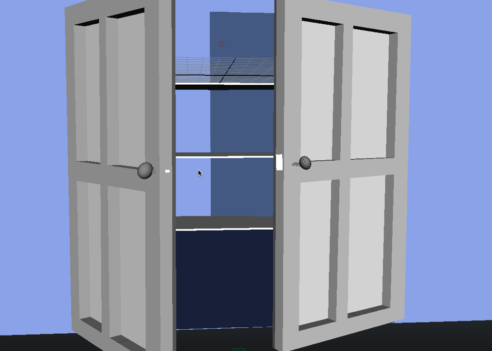
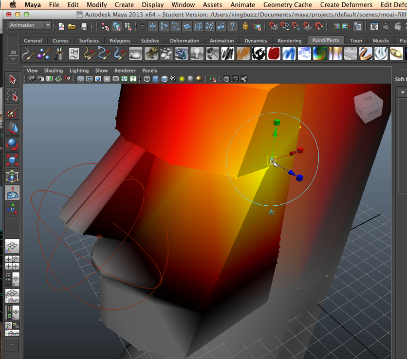
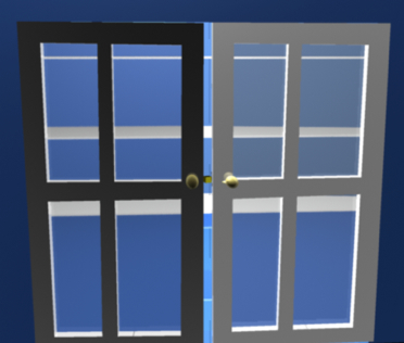
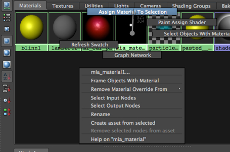
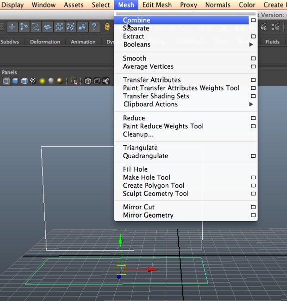
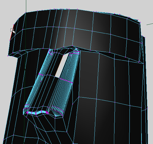
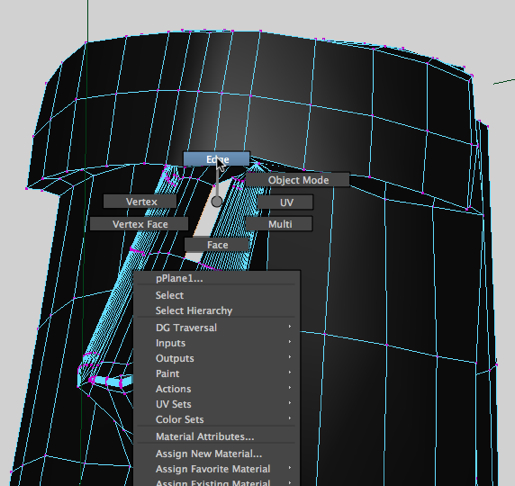
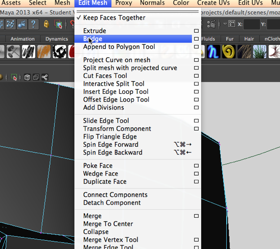
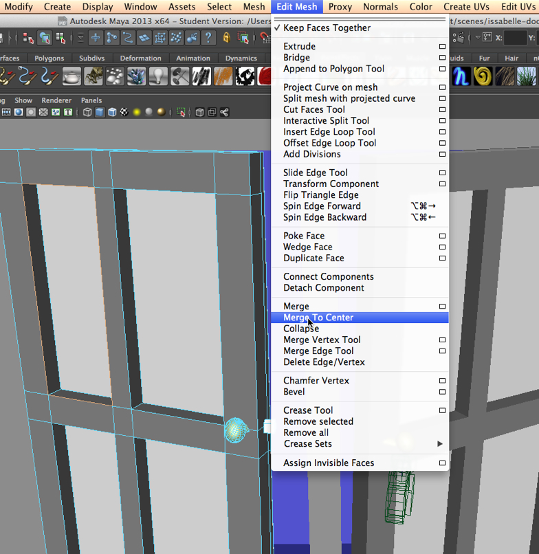
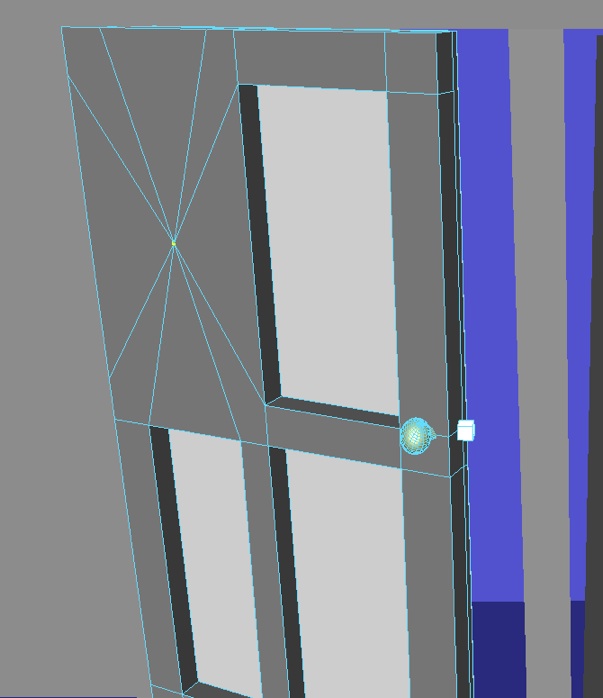
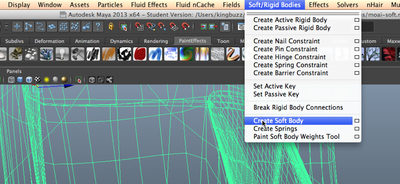
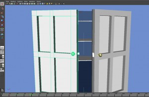
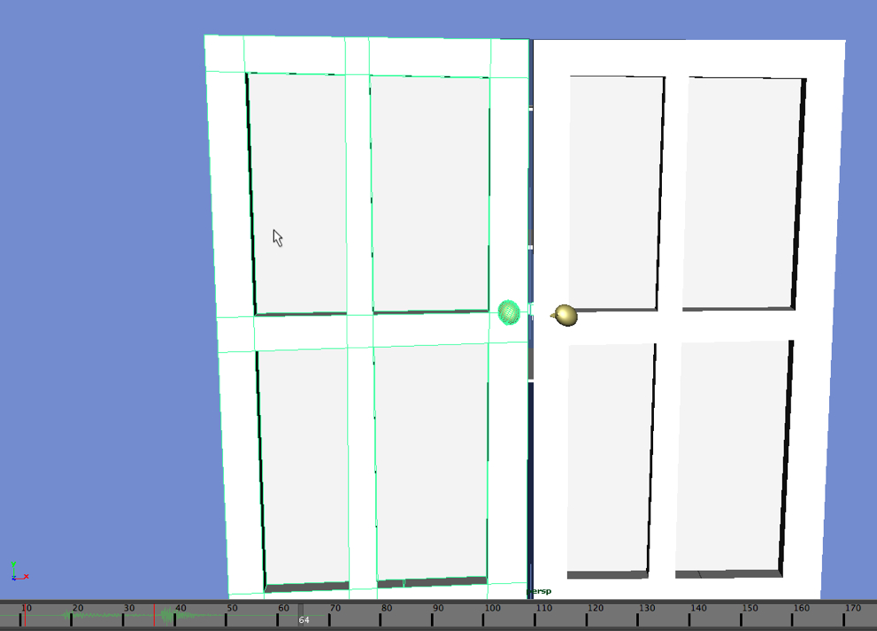
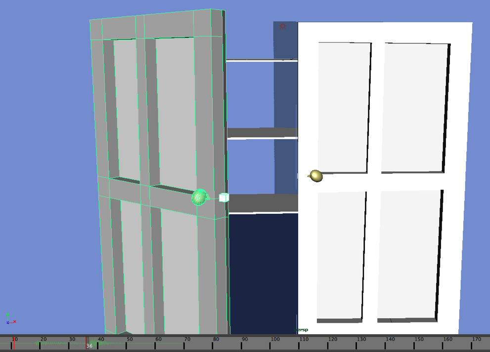
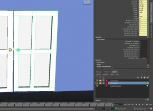
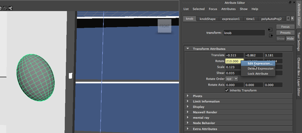
There are many cases in which keyframing the motion of an object is very difficult, in particular, in situations that require precise, cyclic changes in the attribute of an object, or in the relationship between two or more attributes. In the image below, the knob on the door is selected, and then we have right-clicked on the Rotate attribute.  This brings up the Edit Expression option.


knobexpression-2013-02-23-21-17-1.jpg

The expression editor.
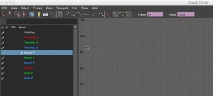
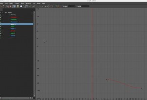
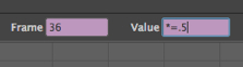
Selecting this in turn brings up the Expression Editor:


expressioneditor-2013-02-23-21-17-1.jpg

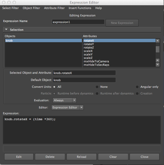
We have entered an expression in the Expression Editor – it tells Maya to change the value of the rotation attribute along the x axis over the course of the frames that appear on the timeline.
Specifically, Maya is told to rotate the knob through an entire 360 degrees.
We then hit Create on the Expression Editor.

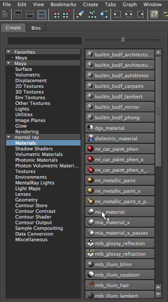
Example 2: Applying an expression to the visibility attribute of an object that has a material with a glow intensity.
Let’s do another example.
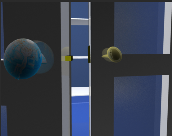
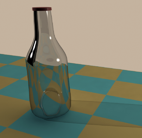
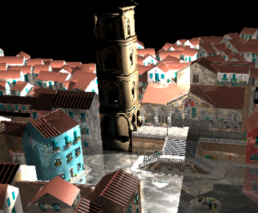
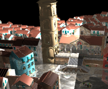
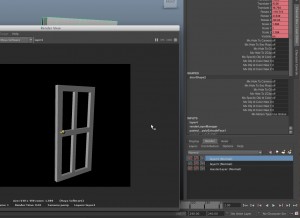
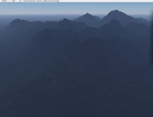
The foggy street.
In the video tutorials on 3DbyBuzz, we made use of a street scene, with a sidewalk, pavement, grass, and fog.  We inserted the of lights of a car.
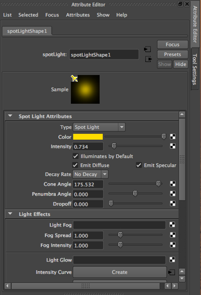
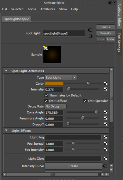
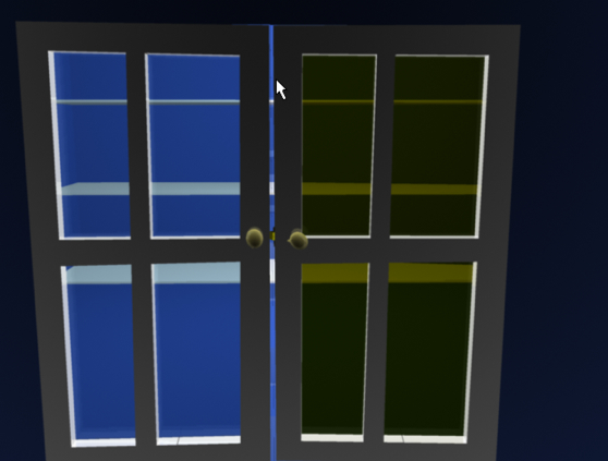
What we’ll do here is color those lights, one red, and one blue, and then have them flash on and off randomly.

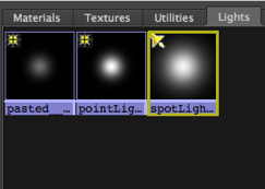
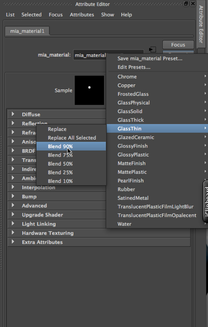
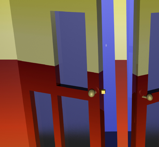
Lights that are not lights.
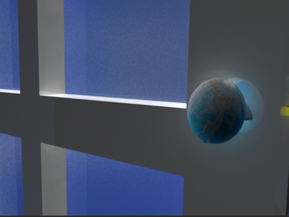
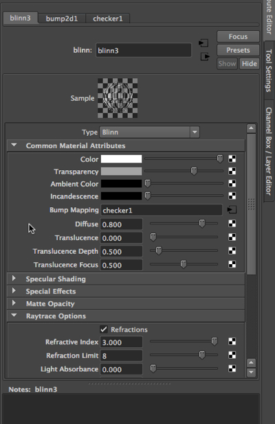
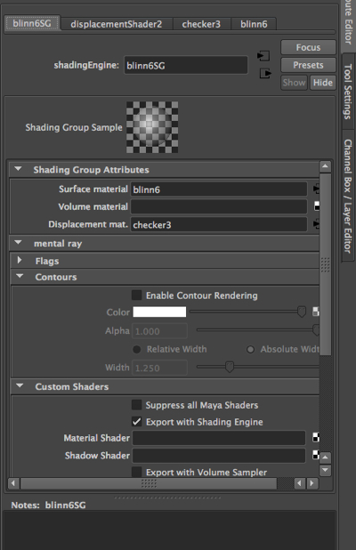
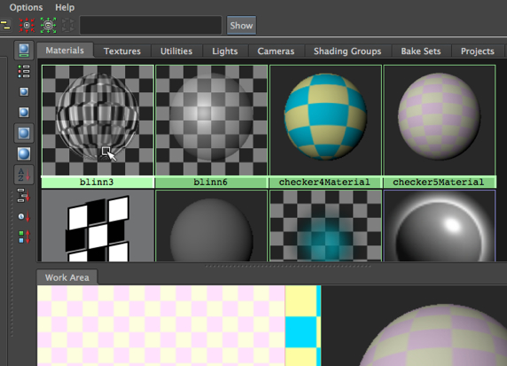
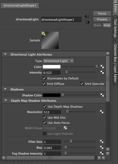
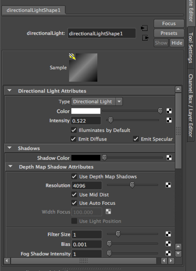
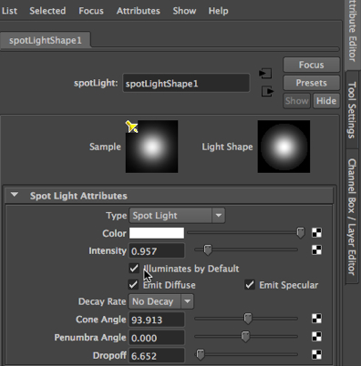
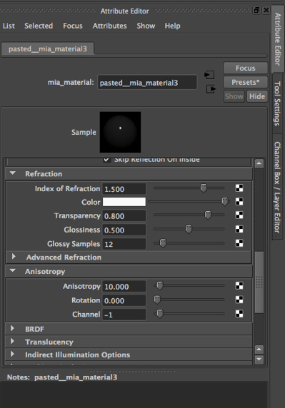
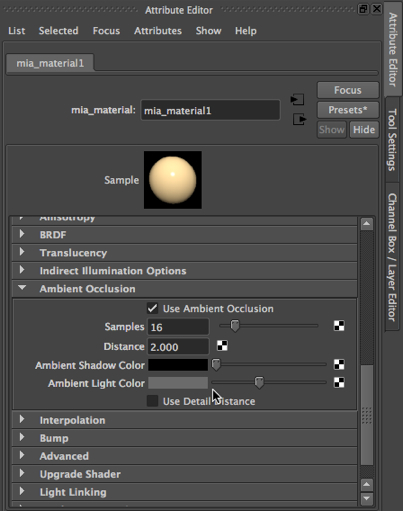
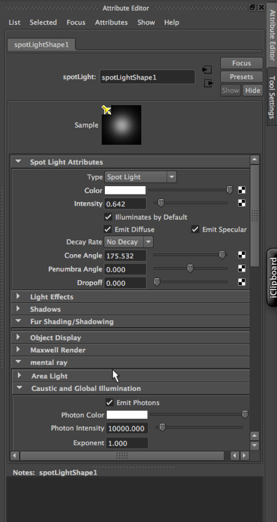
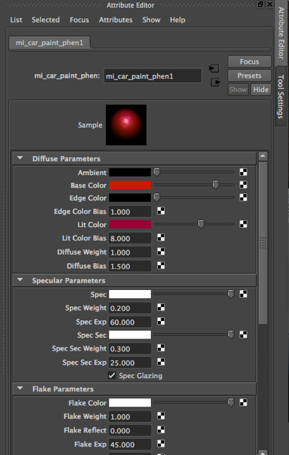
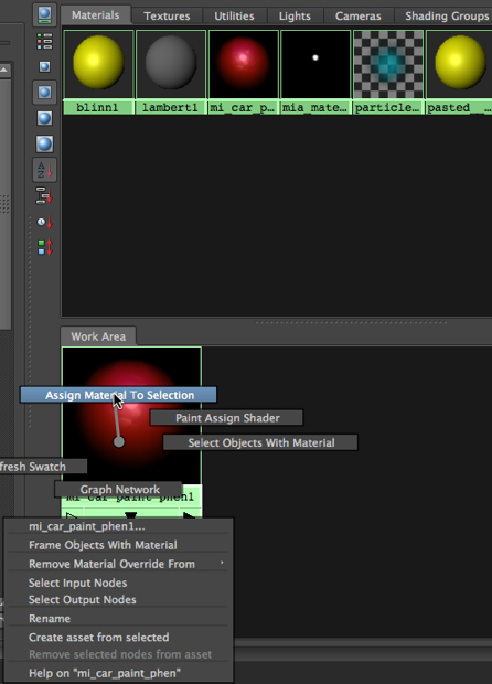
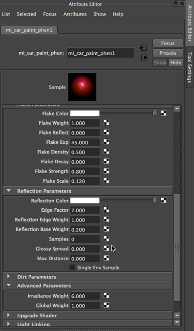
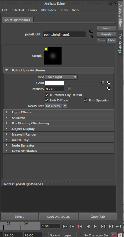
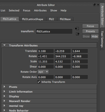
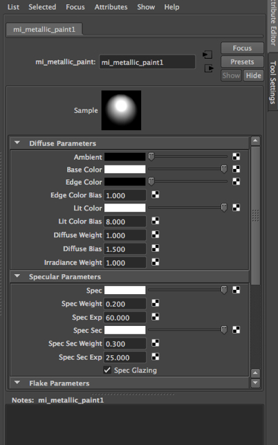
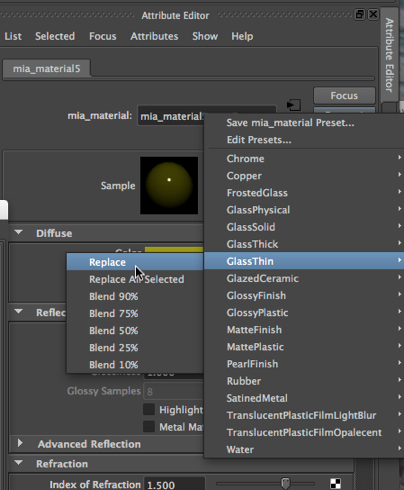
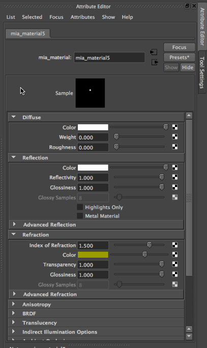
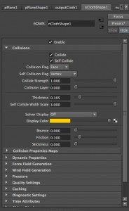
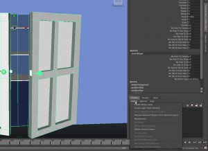
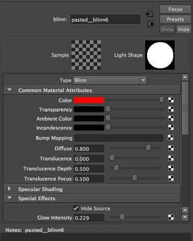
Here’s the important point, though: these “lights” are actually spheres with blinn materials that have a glow intensity.  They are not Maya lights.  Here is the attribute editor after we have selected the blinn material for one of them:


glow-2013-02-23-21-17-1.jpg

What we will apply our expression to is the visibility of the two spheres – not to the material on the spheres.

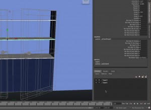
Assigning an expression to the visibility of an object.
Below, one of the spheres has been selected in the main window, and we have opened up the Expression Editor by going to Window at the top of the Main Menu, selecting Animation Editors, and then choosing Expression Editor.  Then we clicked on the visibility attribute in the second column from the left.
Here is the expression after we have typed it in and hit Create:


expression-2013-02-23-21-17-1.jpg

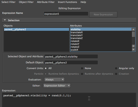
The expression makes use of a random function with reevaluates the visibility of the sphere for every frame.  This is a great function to have – because one of the most difficult things to do is to generate what appears to be random values.

We then must do the same thing to the other sphere.
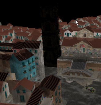
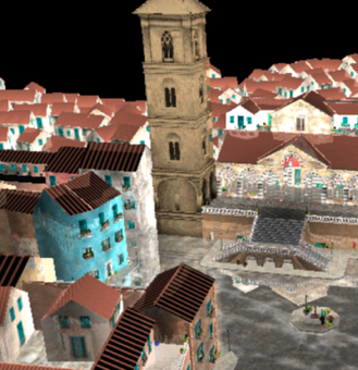
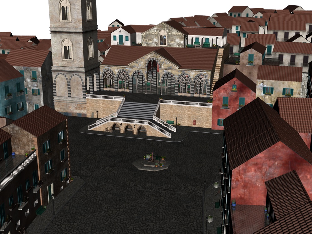
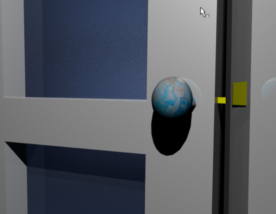
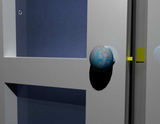
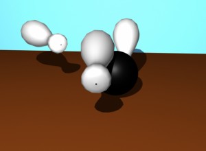
The result.
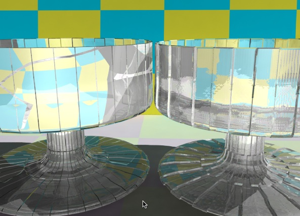
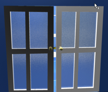
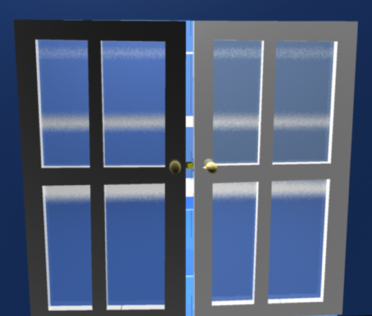
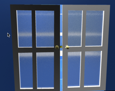
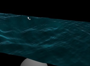
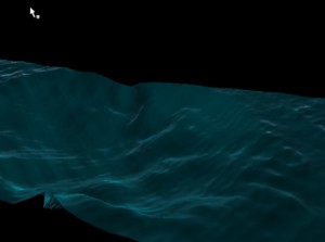
Finally, here is a sequence of three frames, taken across a series of 30 frames:


blueonly-2013-02-23-21-17-1.jpgboth-2013-02-23-21-17-1.jpg

red-2013-02-23-21-17-1.jpg

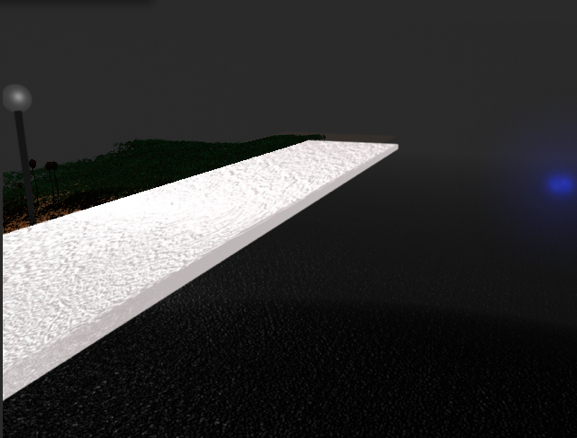
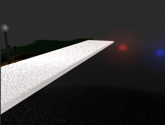
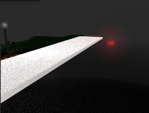
Now, we have flashing emergency lights, perhaps from an approaching police car.


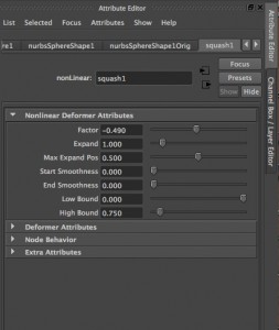
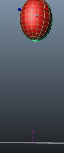
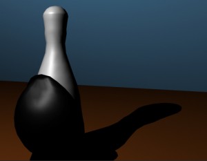
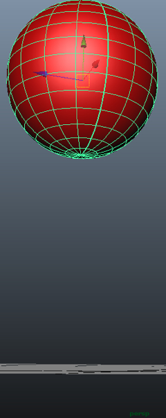
Example 3: our squashing ball.
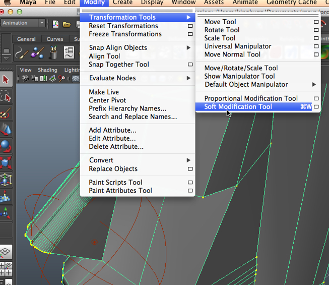
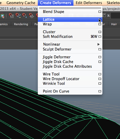
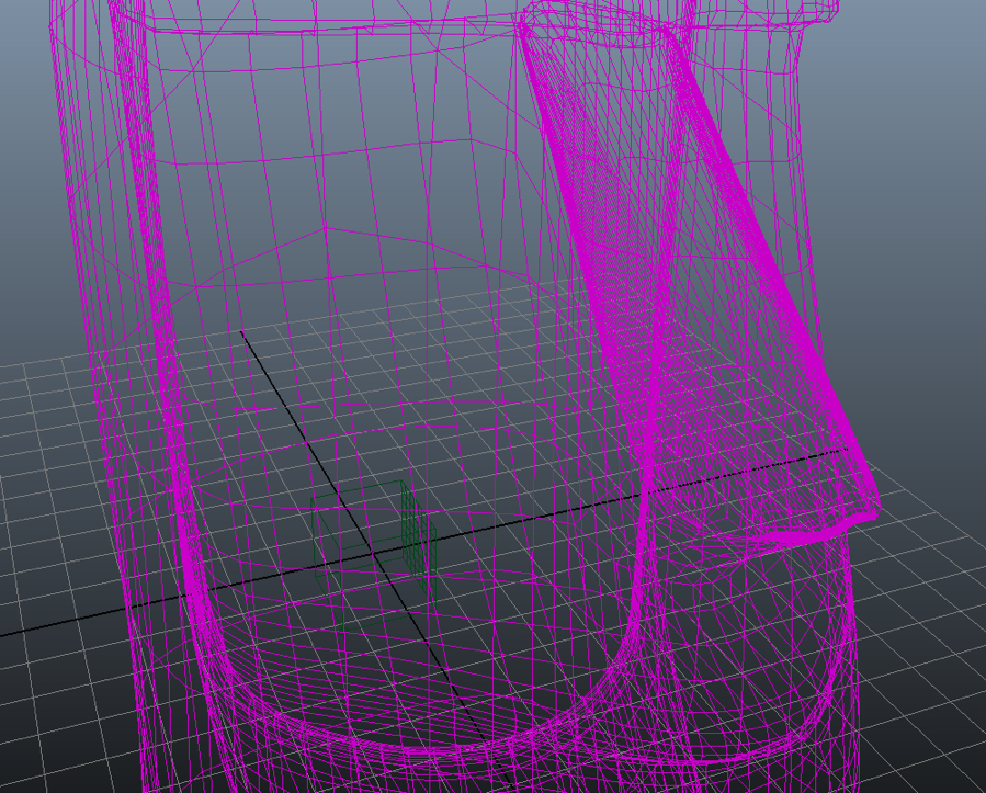
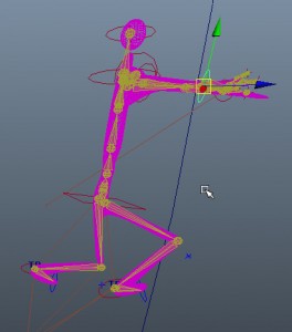
In a previous posting of this blog, we looked at using a Squash deformer to flatten a ball when it hits the ground.
You might remember that we also wanted the ball to stretch out as it rose up.  We did this by using the scale tool and keyframing the ball stretching out as it went up.
We’ll do this again, but in reverse, and not by using the scale tool.  We will use a squash deformer when the ball hits the floor, as we did before.  But we will use an expression to stretch the ball out as it comes down.

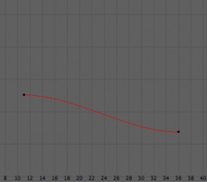
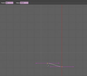
The stretch expression.
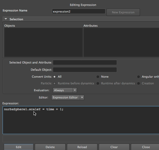
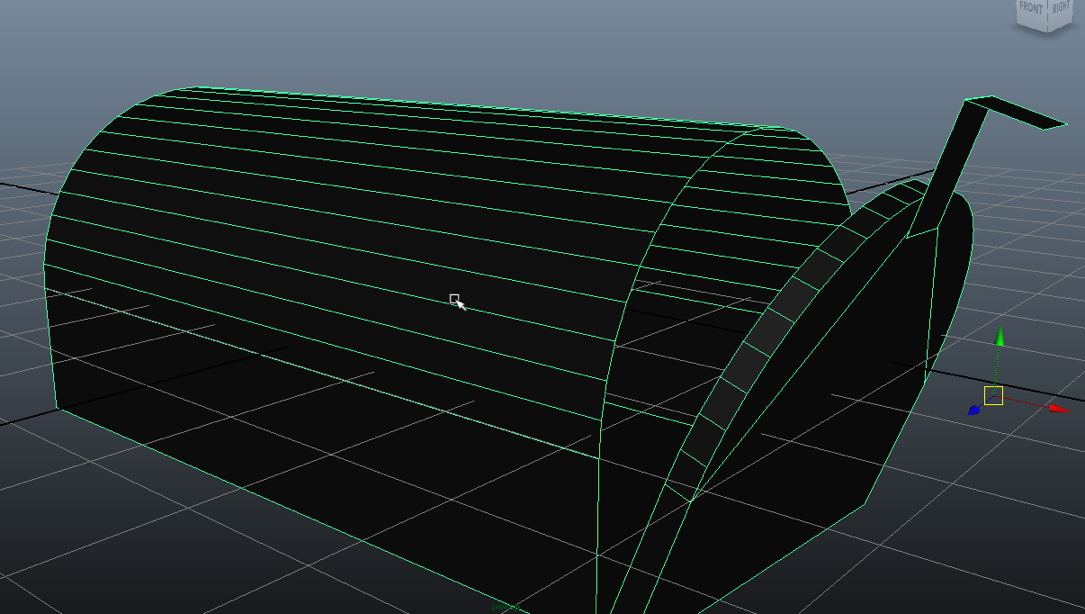
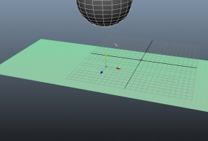
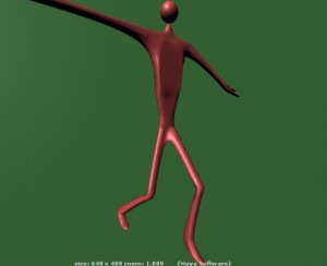
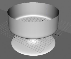
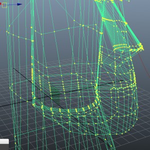
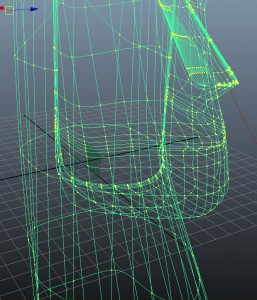
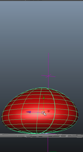
 expressionforball-2013-02-23-21-17-1.jpg

The result.

ballup-2013-02-23-21-17-1.jpg

balldown-2013-02-23-21-17-1.jpg

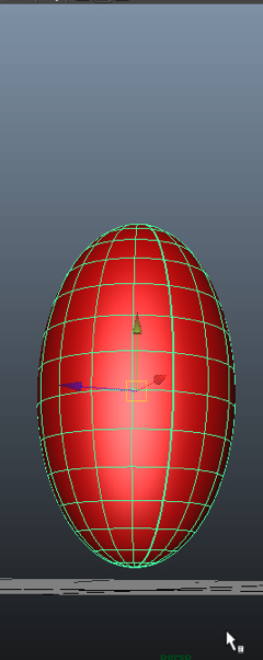
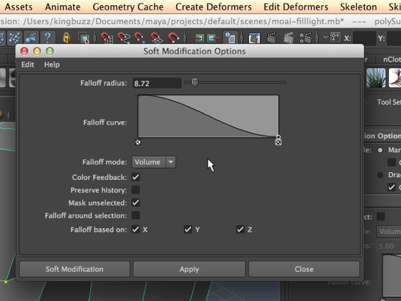
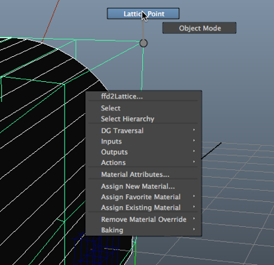
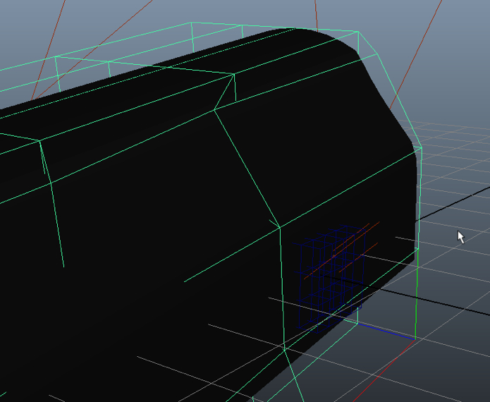
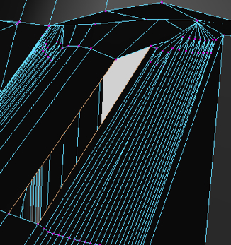
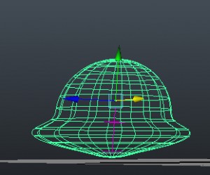
Notice the squash deformer, which we introduce just before the ball hits the ground:

squash1-2013-02-23-21-17-1.jpg

Useful MEL variables and user defined variables.
System variables.
Here are some useful facts about MEL variables:
currentTime is a system variable which contains the current timestamp.
frame is a system variable which holds the current frame number – this is very useful, since expressions get evaluated on every frame.

User defined variables.
Variables created by the programmer, always have a $ in the front, e.g.: int $buzzint;.
Keep in mind that after the $ there has to be a character, and not a number.
Another example of a use variable: float $buzzarray[] = {1.1, 32.2, 23.3, 14.4, 45.6}; 
One more example: matrix $buzzmatrix[9] [2] ; 
There are also local and global variables.

Local variables.

Here are two local variables:
{ int $kingint = 1; int $buzzint = 0; if ($kingint = 1) print ($buzzint); }; The squiggly parens mark the scoping of the two variables.

Global variables.
This program will print the same result as the one above, but it contains a global and a local variable:
global int $kingint = 1; proc buzzproc() { int $buzzint = 0; if ($kingint = 1) print $buzzint; } buzzproc();

Control structures.
Lastly, we note that MEL has a handful of control structures.  Here is an example:
global int $kingint = 1; proc buzzproc() { int $buzzint = 0; while ($buzzint < 3) {print $buzzint; $buzzint = $buzzint – 1; }; } buzzproc();
Note that this program will run forever…

3D animation tutorials

Using anisotropy with mental ray to control the transparency of frosted glass.

In the video tutorials on 3DbyBuzz, we used the mental ray mia_material and its frosted glass preset to create frosted glass doors for a closet.


Anisotropy.
In this posting, we focus on one particular setting for the frosted glass, Anisotropy.
Anisotropy is an attribute that can be set in the mia_material attribute box.  This controls highlights that run across the scene in multiple directions.


Anisotropy settings.
In the image below, we see the Anisotropy settings for the mia_material that makes up the frosted glass of our doors.

anisettings-2013-02-19-22-28.jpg

Set to 1.
Below is a render resulting from an Anisotropy setting of 1, meaning that the left-right and up-down values of the highlights are equal, or more precisely, that the highlights are even in all directions.
Thus, the glass doors blur the white shelves behind them.

ani-1-2013-02-19-22-28.jpg

Set to 10.

Below, the setting is 10, creating a highlight that is not equal in all directions.  In particular, the top-down highlights are softer than the left-right highlights. The effect is to undo some of the frosted effect of the glass, as the highlights don’t blur the shelves as much. You can think of it this way: in order for the horizontal shelves to be distorted to the point of not being easily visible, the white coloring of the shelves needs to be moved upward and downward.


ani-10-2013-02-19-22-28.jpg

Set to 100.

If we crank it up even more, we see that the highlights are very weak in the top-down direction (compared to the left-right direction).  So there is now virtually no frosted glass effect.

ani-100-2013-02-19-22-28.jpg

A number less than 1.

Below, we see what happens if you set the number to .1.  Now, the highlights are greater up-down than they are right-left, and the doors are distorted again.

fraction-2013-02-19-22-28.jpg

3D animation tutorials

Using ambient occlusion with a mental ray material.

In the previous posting of this blog, we looked at a few ways of manipulating light in a Maya scene, focusing on the mental ray renderer.  We looked at global illumination and final gathering, caustics, and irradiance. Now, we look at another way of fine tuning light effects with the mental ray renderer on Maya.

A sample model.

In this lesson, we will use a scene built by Dreamlight.  It is called La Piazza Realistic Mediterranean Town, and was originally built for Daz3d.  I exported it out of Daz3d as an FBX file and then imported it into Maya.  I then replaced the materials on the central tower in the scene with a mia_material that is colored a light tan.  We will only look at a piece of the scene.

Ambient occlusion.

The mia_material has a special setting called Ambient Occlusion:

ao-settings-2013-02-19-19-20.jpg

Without ambient occlusion.

Here is the rendered scene, using mental ray, and with Ambient Occlusion on the mia_material settings not checked off:

without-ao-2013-02-19-19-20.jpg

Note that the left face of the tower is hidden in shadow.

With ambient occlusion.

Here is the same scene with ambient occlusion turned on:

with-ao-2013-02-19-19-20.jpg

Note that now, we can seem much of the detail on the left face of the tower.

What happened?

Importantly, remember that ambient occlusion is a property of the material that is on the tower.  The rest of the scene does not have a mia_material on it. By turning on ambient occlusion, we are telling the mental ray renderer to not let the strong spotlight that falls on the right side of the building wash out the right side and cast the left side into shadow. Importantly, there is a second light in the scene, an ambient light.  When we turn on ambient occlusion, we are telling Maya to pay less attention to the spotlight and to let the effects of ambient light effect the material.

With only ambient light and without ambient occlusion.

Now, here is a rendering where the spotlight has been turned off and ambient occlusion on the mia_material is turned off.  Left click to enlarge it:

onlyambiantlight-noao-2013-02-19-19-20.jpg

Wow!  it turns out that the mia_material, without ambient occlusion, will not accept the effects of ambient light.

With only ambient light and with ambient occlusion.
Now, with only the ambient light turned on, but with ambient occlusion turn on in the attribute editor for the mia_material, we get the following.  Please note that the ambient light had to be made much stronger in order to light up the tower by itself:

withonlyambiant-withao-2013-02-19-19-20.jpg

The lesson.
With ambient occlusion turned on, and with the spotlight turned on, mental ray accepts the effects of ambient light and so the ambient light created by the spotlight and the ambient light illuminates the tower, making the detailed light and shadow of the tower more visible.
With ambient occlusion turned on, and with only the ambient light turned on, the ambient light by itself lights up the tower.

A proper rendering.
Because my manipulation of this scene does not do the artist’s work justice, here is a rendering of the center of the original scene, created by the Daz3D renderer.  Left click on the image to enlarge it:

medtown3-2013-02-19-19-20.jpg

3D animation tutorials

Global illumination, final gathering, caustics, and light emitting materials in Maya, using mental ray.

In the video tutorials on 3DbyBuzz, we look at the basics of creating lights in Maya, using ray tracing, and manipulating shadows.  We also look at the rudiments of global illumination and final gathering.  And we look at depth map versus ray traced shadows. In this posting, we review final gathering and then look at a couple of new things: caustics and irradiance.  Our goal is to look at a few different ways of adding light effects to a scene. We will be using the mental ray renderer for this posting.

Global illumination and final gathering.

We use these two options to add more light to darkened areas of a scene. As a reminder, final gathering, which is an option you can set in the mental ray renderer, adds some extra computations to the ray tracer, and in doing so, fills in dark areas.  These often occur when one part of a model is casting a shadow on itself.  By using final gathering, we put some extra rays in those little spots. If we go to Window, choose Render Editors, and then Render View, we can select mental ray, and then go to the Indirect Lighting tab and choose Global Illumination. We will also turn on Final Gathering, which does a similar job, but is less effective.


globalillandfg-2013-02-16-22-21.jpg

 Below, is the before and after. Without global illumination and final gathering.  Notice the area around the brass bolt.


none4-2013-02-16-22-21.jpg

  With global illumination and final gathering.  Look at the same area:


withgifg2-2013-02-16-22-21.jpg

Caustics.

We use caustics to create the harsh light reflections and refractions we often get when light hits a glass object. We will manipulate both the lights in a scene and the mental ray settings to get caustics. We will use a scene that we have seen in the tutorials on 3DbyBuzz.  We have a NURBS curve that has been revolved to make a dish.  On it we have placed the mental ray mia_material, with a ThickGlass preset:


mia_material-2013-02-16-22-21.jpg

We apply this material to the dish by selecting the dish in the Main window, then right clicking on the material, and then assigning it:


assigningglass-2013-02-16-22-21.jpg

 First, here is a scene without caustics:


withoutcaustics-2013-02-16-22-21.jpg

  Now, we turn on Caustics in the mental ray render settings:


causticsinmrsettings1-2013-02-16-22-21.jpg

Now, we turn on photon emitting in the attributes of the dominant light in the scene, which happens to be a spot light with a wide cone.  The other light in the scene is also a spotlight with a wide cone, but its intensity is much lower.


photonsinlight-2013-02-16-22-21.jpg

  Now, we render the scene again:


causticswithlessintensity-2013-02-16-22-21.jpg

 Light emitting materials: Irradiance.

First, we choose a highly reflective material from the mental ray list of materials.


miapaintmaterial-2013-02-16-22-21.jpg

We apply this material to the dish by selecting the dish in the Main window, then right clicking on the material, and then assigning it:


redpaintmaterial-2013-02-16-22-21.jpg

Now, we turn our two spotlights in the scene down low and render. There is very little light in the scene:


dimred-2013-02-16-22-21.jpg

Now, we turn up the irradiance of the material.


irradiancelevel-2013-02-16-22-21.jpg
Below is the result.  We have a sci-fi goblet.


irrandianceglow-2013-02-16-22-21.jpg

3D animation tutorials

Placing fill lights in a Maya scene.

Lights in Maya.

In the video tutorials on 3DbyBuzz, we have looked at creating the various kinds of light that are available in Maya.  One thing we have not looked at is using lights as precise, local fill lights.

Fill lights.

We create lights by going to Create on the Main Menu and going to Lights. Here is a rendering of the Moai statue we have used in the videos.  The only light is a directional light.

moaicloseupshadow-2013-02-12-17-20.jpg

Softening the nose shadow.

Now, we create a point light and locate it near the left bridge of the nose.

pointlight-2013-02-12-17-20-1.jpg

pointfilllightinuse-2013-02-12-17-20-1.jpg

We have softened the shadow.

But, what about Volume lights?

You might think that the best kind of light to use for very refined control would be a Volume light that is set to shine inward:

usingavolumelight1-2013-02-12-17-20.jpg

But the problem is that Maya 2013 seems to have a lot of trouble rendering volume lights with either the Maya software renderer or Mental Ray.  It simple seems that the light does not exist. But if we want to use the Hardware renderer, it will work:

hardwarerender-2013-02-12-17-20-1.jpg

3D animation tutorials

Using the Append to Polygon tool for connecting two stairs.

Connecting two carpeted stairs.

In one of the videos on 3DbyBuzz, we looked at connecting two carped stairs and noted that we have to model the offset of the front face of the top step from the bottom step, so that the carpet would pull backward over the lip of the top step.  We used NURBS tools to do this.

Polygon stairs.

Here we take a quick look at doing a similar thing with polygon modeling. First, we create the two planes need for two steps. Importantly, we must use the Combine tool and create one object out of the two.  This tool is found by changing the Main Menu Selector in the upper left corner of the main Maya window to Polygons.  Then we choose Mesh and then select Combine.


combiningtwoplanes-2013-02-12-16-01.jpg

The planes are not connected yet, but they are one object.

The Append to Polygon tool.

Now, we go to Edit Mesh and select Append to Polygon Tool.


appendtopolygontool-2013-02-12-16-01.jpg

  Then we select the two edges of the two polygons that are closest together.

selectingedges1-2013-02-12-16-01.jpg

Then we hit Enter – and the two planes are connected by an angled polygon, creating the the offset of the carpet from the front of one step to the top of the other.


appendedplanes-2013-02-12-16-01.jpg

3D animation tutorials

Using the Lattice Deformer to damage our mailbox.

Deformers.

In the tutorial videos on 3DbyBuzz, we have looked at the use of deformers to alter that shape of an object, either for the sake of creating the model itself or to deform and thereby animate the shape of an object over a series of frames.

The Lattice deformer.

In this posting we look at a deformer we have not examined yet: the Lattice deformer. The deformers can be found by setting the Main Menu Selector on the upper left hand side of the Main Maya window to Animation.  We then go to the Create Deformers dropdown. We choose Lattice Deformer:

latticedeformer-2013-02-12-15-18.jpg

The tool settings.

Here are the settings for the tool, which we get if we click on the little square box to the right of the Lattice entry on the Create Deformers dropdown:


latticetoolsettings-2013-02-12-15-18.jpg

Notice that there is an advantage to manipulating the mailbox via a lattice deformer instead of by manipulating the wireframe of the object itself: we can control the area over the surface of our mailbox that is deformed by adjusting the divisions and other settings of the deformer – and not by actually altering the density of geometry of the object.


lattice-2013-02-12-15-18.jpg

Vertex mode on the deformer.
Now, we select vertices on the deformer and move them.  (They are called Lattice Points, not vertices, actually.)


latticepointmode-2013-02-12-15-18.jpg

The result.
After we move the lattice points, we get:


dentedmailbox-2013-02-12-15-18.jpg

A note on the deformer tool.
Here are the tabs that appear when we create the lattice deformer.  Note that there is a tab named ffd2Lattice.  (The 2 merely means that this is the second lattice deformer I created in the scene.)
When you change the shape of the lattice by moving lattice points around, you change the values under the ffd2Lattice tab, and this in turn alters the shape of the model.  You can update the values under the tab (instead of moving points around) and this will alter the model.


twolatticetabs-2013-02-12-15-18.jpg

3D animation tutorials

Filling in a face on the Moai with the Bridge tool

Filling in a hole in a polygon model.

In recent postings, we’ve been looking at using various polygon tools to manipulate a polygon model.  Today, we look at fixing a hole in a model.

The hole.

Sometimes, as we manipulate a polygon object, having been doing such things as adding and removing edges, extruding faces, combining multiple polygon objects into a single object, etc., we discover a hole where we need a face. Consider the Moai below, which we have used in the 3DbyBuzz video tutorials. There is a missing polygon on the side of the nose.


missingface-2013-02-9-20-17.jpg

Edges and bridging. So, we right click and go into edges mode.


edgemode-2013-02-9-20-17.jpg

Then we select two edges.  Then,we select the Bridge tool from the Edit Mesh drop-down.  (Note that we have to have the Main Menu Selector in the upper left corner of the Maya interface set to Polygons.)


Iedgesselected-2013-02-9-20-17.jpgbridgetool-2013-02-9-20-17.jpg

Too many polygons.

We succeeded in filling in the hole, but there are multiple faces where we only want one.


result1-2013-02-9-20-17.jpg

  So, we hit control-z until we undo the Bridge operation.  Then we select the Bridge tool again, and this time click on the little box to the right of the tool’s name and pull up its settings.  We chance the number of subdivisions to 0 and try again.


bridgetoolselected-2013-02-9-20-17.jpg

The hole filled in with one face. It worked.


result2-2013-02-9-20-17.jpg

Final note.
One caveat — when you use the Bridge tool, all selected edges must be on the same object.

3D animation tutorials

Removing a window with Merge to Center

Removing a window.
In the previous blog posting, we looked at merging edges.  In this posting, we use another tool on the same drop-down menu: Merge to Center, and we use it to move a window from a glass door.
Here are the closet doors we’ve used in the tutorials in 3DbyBuzz:

glassdoors-2013-02-8-23-41.jpg

Choosing four edges and the tool.
We select four edges around the window.  (They are in orange and surround the upper left window of the left door.)  Then we choose the tool:

mergetocentertool-2013-02-8-23-41.jpg

The result.

mergedtocenter-2013-02-8-23-41.jpg

The result rendered.

resultrendered1-2013-02-8-23-41.jpg

3D animation tutorials

Merging edges in a single piece of geometry

Fixing a mailbox.

In one of the 3dbybuzz videos, we made a mailbox out of a single polygon object.  We created a lid by selecting a ring of vertices and separating the object into two pieces.  Note that it remained one object:

mailboxopen-2013-02-8-21-52-1.jpg

The problem is that the bottom edge is separated from the rest of the mailbox:

mailboxbottom-2013-02-8-21-52-1.jpg

Perhaps we should have left that edge connected so that we could more naturally animate the mailbox.


The Merge Edges tool.
So, we put the Main Menu Selector on Polygons, then we go to Edit Mesh and select the Merge Edges tool.


mailboxlinedup-2013-02-8-21-52-1.jpg mergeedgetool-2013-02-8-21-52-1.jpg

We then select the two edges along the bottom that connect the lid to the body of the mailbox.  Then hit Enter.

firstedge-2013-02-8-21-52.jpg

Before and after.

before-2013-02-8-21-52-1.jpg

Above is the before hitting Enter…  Below is after hitting Enter.

after-2013-02-8-21-52-1.jpg

3D animation tutorials

Coloring a material with lights

In the previous posting we looked at using a Mental Ray material to make colored glass.  We manipulated a color attribute of the material.

Coloring the light, not the material.

In this posting, we color a bowl by using the lights that are shining on it. Here is the Mental Ray material’s attributes; we are using one of the metallic paint materials:


colorofmaterial-2013-02-5-22-55.jpg

Note that the colors of the material are all set to white.

The lights.

There are two spot lights shining on the bowl.  They are between the bowl and the viewer, pointing directly at the bowl. Here are their attributes:


goldlight1-2013-02-5-22-55.jpg

goldlight2-2013-02-5-22-55.jpg

Notice that we are using two different yellow-ish colors. (Note that the brown background is not influencing the color of the bowl.)

The result. Here is the rendering:


goldrendering-2013-02-5-22-55.jpg

3D animation tutorials

Making colored glass in Maya with Mental Ray

In this posting, we will make a colored glass door for the closet we used in some of the video tutorials on 3DbyBuzz.

Mental Ray glass material.

First, we go to Window on the Main Menu, then choose Rendering Editors, and then Hypershade.

Then we go to the list below the words “mental ray” in the hypershade and create an instance of a material called mia_material.

miamaterial-2013-02-5-22-05.jpg

Coloring the glass.

We go to the Main window choose the preset GlassThin for our material, and we select Replace:

thinglasssettings-2013-02-5-22-05.jpg

Then we click on the Refraction color and set it to a dark yellow:

coloredglass-2013-02-5-22-05.jpg

Assigning it to the glass door.

Then we shift-select the four panes on our right hand door, go to the Hypershade, and then right click on the material and hit Assign Material to Selection.

The result.

Then we render with the Mental Ray renderer:

coloredglassdoor-2013-02-5-22-05.jpg


3D animation tutorials

Using soft body dynamics to age a Moai statue

Today, we look at using soft body dynamics to age a Moai statue.
The polygon Moai.
Here is the Moai statue that we have used in videos on  3DbyBuzz.com.  It was made out of stone a long time ago.  It has sat in the open on a wind-swept, treeless island for many hundreds of years.        moaisoft-2013-02-5-18-10.jpg
Turning the Moai into a soft body.
We set the Main Menu selector in the top left corner of the Maya Main Window to Dynamics.
Then we select the Moai, go to Soft/Rigid Bodies and choose Create Soft Body.
Now, our Moai will be influenced by dynamic forces.

softobjectdropdown-2013-02-5-18-10.jpg

Introducing a field.
Now, with the Moai selected, we go to Fields and Select Turbulence.  It is not shown here, but the Magnitude of the field is about 40 – not too strong.  We don’t want to blast our Moai away.  Also, the Phase x and Phase y settings of the Turbulance tool are set to -1.

turbulance-2013-02-5-18-10.jpg

Before and after.
This is the Moai before running the scene:

beforeworn-2013-02-5-18-10.jpg

Here is the Moai after running about 100 frames.
The turbulence has gently eroded the nose and the mouth and the jaw.
afterworn2-2013-02-5-18-10.jpg
If we want, we can move the turbulence field around and age more of the Moai’s face.

3D animation tutorials

Using the Graph Editor in Maya to fine tool animation

Maya’s Graph Editor. In the videos at 3DbyBuzz, we’ve looked at the Graph Editor and how it can be used to adjust motion and to reuse motion cycles.  Here, we look at one specific feature of the Graph Editor and how it can be used to fine tune the keyframing of objects in your scene. (Note: left click on images below to enlarge them in your browser.) This is the top of the Graph Editor:

grapheditortop-300x135-2013-02-3-16-49.jpg

Frame and Value.
Notice the two boxes in the upper right corner.  When they have values in them, they are pinkish-purple.  Values appear in there whenever some curve in the Graph Editor is selected.
Remember that the Graph Editor shows the Translation (movement), Rotation, and Scaling of objects in your scene as the frames go by.  The Frame box gives you a frame number and the Value box gives you the value of a given point.
Our closet.
Below is the closet that we have used in a few of the 3DbyBuzz videos.  Notice that the left door is selected.
closetopen-300x196-2013-02-3-16-49.jpgIf you left click on the closet, you will see that two keyframes (in red) are showing down on the Timeline.  The first is when the left door starts to move and the second is when it shuts.
The rotation curve.
In the image below, we see that the Rotate x curve is visible.  This tells us how the door rotates over a series of frames.  In the image, it is moving between frame 11 and frame 36,  just as our keyframes in the image above suggest.
rotationcurve1-300x204-2013-02-3-16-49.jpg
Here is a closeup of that curve:

rotationcurve2-300x264-2013-02-3-16-49.jpg

The Rotation Curve
This is what the curve looks like if we click on Frame 36 on the Timeline and then select the curve in the Graph Editor:

frame36oncurve-300x261-2013-02-3-16-49.jpg

Notice that the frame number is showing in the Frame box.
Here is what the scene looks like on Frame 36.

closeclosed-2013-02-3-16-49.jpg

Changing the number of frames it takes to close the door.
Notice that the vertical red line tells us what frame appears in the Frame box.  Let’s change the keyframing so the door closes only part of the way.  Here is what we put into the Value box:

closedoorhalfway-2013-02-3-16-49.jpg

The effect.
Here is what happens after we press Enter.

cloorhalfclose-2013-02-3-16-49.jpg

In general we can add, subtract, multiple, and divide values by adding expressions to the Value box.  Here, we have made the door close only halfway instead of all the way.

3D animation tutorials

Creating an ocean water swell in Maya

We will create a swell of water that ripples outward in Maya. The setup. Below is a polygon plane that has a high vertex count.  Above it is a polygon sphere.

watersplashsetup-300x203-2013-02-2-23-14-1.jpg

The ocean is made of cloth.
Here is the attribute editor of the plane.  This is after selecting the plane and setting the Main Menu Selector to nDynamics, then going to nMesh and selecting Create nCloth.  The vertices of the plane have been turned into particles.

clothattributes-184x300-2013-02-2-23-14-1.jpg

The ball is under the power of gravity.
Next, we place the ball above the plane, select the ball, and then select Fields, then Gravity.  (You might want to check the attributes of the gravity field to make sure it is going downward in the  y dimension, in case the default is set otherwise.)
The plane has an ocean shader on it.
Then we go to Window, choose Rendering Editors, then Hypershade.  Then click on the Ocean Shader to make an instance of it.

oceanshader-300x261-2013-02-2-23-14-1.jpg

Next, we select the plane in the Main window.  Then we select the ocean shader in the Hypershade, right click, and choose Assign Material to Selection.
The ball falls through the water.
Then we set the scene up with perhaps 200 frames.  We then play the scene, with the ball starting up in the air and falling through the plane.
Here is what it looks like after the ball passes through.

watersplashthrough-300x203-2013-02-2-23-14-1.jpg

The water creates a rippling swell.
As the scene continues, the water develops a deep swell that ripples.
Here are three frames.  The first is BEFORE the ball falls.  The second is after the ball has just passed through, and the third is a number of frames later:

splashstage1-300x223-2013-02-2-23-14-1.jpg

splashstage2-300x223-2013-02-2-23-14-1.jpg

splashstage3-300x223-2013-02-2-23-14-1.jpg


3D animation tutorials

Bouncing a squishy ball

We will use a deformer, the scale tool, and keyframing to bounce a ball so that it squishes on the ground and then stretches as it bounces up. (You can left click on any image below to blow it up.) The ball. First we create a NURBS ball. The Squish Deformer. Then we select the ball and create a Squash deformer from Create Deformers (on the Main Menu with the Main Menu Selector set to Animation).

squashsettings-253x300-2013-02-2-20-23.jpg

Squish the ball. We then place the ball on the lower plane and then select the deformer.  We use the move tool to lower the pink deformer handle inside the ball to squish the ball.

squashedball-300x249-2013-02-2-20-23.jpg

  Keyframe the ball. We then keyframe the ball to go up and down over a series of at least 75 frames (so we can easily see it move and deform).  This is how we set the keyframes: Stretch the ball. We start at the top and set the first keyframe there (with the s key). But before we set the keyframe, we  use the scale tool to stretch the ball out top-to-bottom. Bounce the ball. Then we go to frame 30 or so, move the ball to the ground (and the deformer will automatically squish it for us).  We set the second keyframe it there. Stretch the ball. Then we keyframe it at the top again, at perhaps keyframe 75. But again, before we set the keyframe, we  use the scale tool to stretch it out top-to-bottom again. Run the scene. We see it fall and squish, then bounce and stretch.  Maya even makes it stretch gradually as it moves upward.

ballstretch-126x300-2013-02-2-20-23.jpg

ballbottomsquish-126x300-2013-02-2-20-23.jpg

3D animation tutorials

A start on layers in Maya

There are three kinds of layers in Maya, and we will quickly overview them here, and then look at them in more detail in future postings of this blog. Please note: you might want to left click on the images below to see them blown up in your browser. Our Model. We will use a closet with moving doors that we used in a few of the tutorials on 3dbybuzz.  Here is the rendered model:

layers-closet-300x221-2013-01-29-22-28.jpg

Layers controls.
All three kinds of layers can be accessed in the lower right hand corner of the Main Maya window, below the channel editor.  You might have to hit control-a, which toggles between the attribute editor and the channel editor.

layers-display-300x218-2013-01-29-22-28.jpg

Display layers.
The first kind of layer helps us decide what we want to see in a complex scene we are developing.  We can select objects and then create a layer out of those objects.  In our example, we choose to only see a layer that has the shelves and sides of the closet in it, and not the doors of the closet.

layers-display2-300x218-2013-01-29-22-28.jpg

Rendering layers.
The second kind of layer lets us choose objects, put them in layers, and then decide which layers we want to render.  This allows us to remove items in a scene that might be very time consuming to render, and allow us to focus only on more quickly rendered items.
It also allows us to render one layer of a scene and finalize that layer, and then continue to re-render other layers until we like them.  We then compose the layers in our video editing application.
We can also use render layers so that we can render different parts of our scene with different renderers.
There are also a number of other things that can be done with layers.  We can make multiple render layers so that we can carefully control the light and color effects in a scene.
Below, we render only the right hand door.

layers-render-300x218-2013-01-29-22-28.jpg

Animation layers.
Animation layers can be used to carefully blend different forms of animation in a single scene.  It also allows us to carefully reuse existing animation in a new context.
Here is a look at how to create animation layers.

layers-anim-300x218-2013-01-29-22-28.jpg

We will continue with this in future postings.

3D animation tutorials

Making Your Character’s Body More Organic

Our skinny man. In the 3DbyBuzz tutorials we looked at the Maya skeleton generator, and at doing a soft bind of our skinny man to the skeleton.  We stopped there, but there is more that we could do, and there will be posts in this blog in the future covering these techniques. Here he is:

skinnymanik-264x300-2013-01-28-12-22.jpg


skinnymanrendered-300x244-2013-01-28-12-22.jpg

This posting is a preview of what we can do to create a more organic, natural looking binding.  The key is to simulate the varying sorts of tissue that lies beneath our skin. These include muscles, bones, and joints. What’s wrong? Our character is far from natural looking.  With respect to hardness, he appears to have completely homogeneous tissue.  He’s a rubber man.  Real people have muscles, along with solid bones, both of which can be seen beneath our skin. The Maya muscle system. All of this can be simulated by use the Maya muscle system.  The muscle system can be accessed by setting the Main Menu Selector to Animation, and then going to the Muscle dropdown on the Main Menu. Capsules. Maya has something called “capsules” which are rigid and can be used to make a joint appear solid.  Keep in mind that joints themselves do not have any geometry, and so we use capsules to make it appear that a joint has actual geometry.  We can convert joints to capsules. Bones. Maya also has “bones” which serve a very similar purpose, and are created from polygon geometry, and so their shape can be carefully controlled by the animator.  (These bones have nothing to do with the bones that get laid down between joints as we build a skeleton.)  Like capsules, bones can be created by conversion; we turn joints to bones. Muscles. In Maya, bones and/or capsules are used to create “muscles”, which are attached beneath the surface of your character’s skin.  They will cause the skin to deform.  Each muscle is connected in two places (to capsules and/or bones), and when the limb is extended, the two connection points will move apart and the muscle will extend itself.  As the limb is closed, the two connection points will move closer and the muscle will bulge outward. It’s not trivial to use. The Maya muscle system is difficult to master and calls for a lot of iteration. One thing to note is that making a smooth binding look realistic by inserting muscle tissue is a complex problem.  Muscles are not completely rigid.  They are semi-rigid, and not all muscles extend and bulge in the same way.  Muscles also move as coordinated groups as the human body moves.  All the while, the skin moves over the muscles in a semi-independent fashion, but it does not float freely over the underlying tissue. Cloth. Finally, there is some similarity between muscle/skin/bone systems and the sorts of movement that can be engineered using blend shapes and/or cloth.  

3D animation tutorials

Creating a soft bowling ball with nCloth.

Bowling. In one of the videos on 3DbyBuzz, we created a bowling ball and pins. Pins and ball. The pins were made by creating a curved line.  We did this by using the Create Main Menu selector and then using the CV Curve tool to make the profile of a bowling pin.  We then adjusted the Main Menu Selector at the top left of the Maya Main window to choose Surfaces on the main Menu, and then chose Revolve. We then created a polygon ball. Rigid objects. Then the pins and the ball were all turned into active rigid objects by selecting them and then choosing Dynamics from the Main Menu Selector at the upper left of the main Maya window, and choosing Soft/Rigid Bodies, and then choosing Create Active Rigid Bodies. Sideways gravity. Then we put the bowling ball under the power of a gravity field set to move objects in the z dimension, not the y dimension, as gravity normally behaves.  This is done by going to Fields and then choosing Gravity, and then adjusting the direction attributes accordingly. This is the result when we run the scene:

bowlrigid-300x220-2013-01-27-17-52.jpg

nCloth. Now, lets do this again, but this time, we are using the nDynamics Main Menu selection.  We select our pins and then choose nMesh and then Create Passive Collider.  We then select the ball and choose nMesh and then Create nCloth.  (The ball must be a polygon ball for this.)
bowlsoft-300x233-2013-01-27-17-52.jpg
We see the bowling ball squashing when it hits a pin.

3D animation tutorials

Depth map versus ray traced shadows

This is a quick lesson. A glass bowl. The scene below shows a bowl that we have worked with in the 3DbyBuzz video tutorials.  It has a Mental Ray mia material on it, set to GlassThin.

glass-model-300x249-2013-01-26-22-22.jpg

The floor and the wall both have the checkerboard 2D texture from the Hypershade. Add light. There are two lights in the scene, one coming from the upper right and another coming from the upper left.  Both are spot lights.  The light on the right is far brighter than the one on the left. Thus, when we render the scene (with the Mental Ray renderer), we would expect to get a shadow cast to the left. Depth map shadows. Here is what happens when we select the light on the right, go to its attributes (you might have to hit control-a), then go to Depth Map Shadow Attributes and click Use Depth Map Shadows:

depthmap-300x223-2013-01-26-22-22.jpg

  Raytraced shadows. Now, if we go back to the attributes of the right hand light, and go to Raytrace Shadow Attributes and click Use Ray Trace Shadows (which toggles the Depth Map shadows off), we get:

raytrace-300x223-2013-01-26-22-22.jpg

Notice how much softer the ray traced shadows are.
Ray tracing as a light attribute.
We see here that ray tracing isn’t only a setting that we can adjust in the Mental Ray renderer.  Ray tracing can also be turned on in the shadow properties of each light.
Depth map shadows are calculated by tracing each light ray (or photon) across the scene once, thus casting a black shadow, even though the dish is made of glass.  Ray traced shadows are based on more calculations, as light reflects and refracts.

3D animation tutorials

An intriguing way to smooth a polygon model

In the 3DbyBuzz training videos, we cover a few different ways to smooth polygon models. An intriguing smoothing option. There is yet another method, one that only works with the Mental Ray renderer (not the Software Renderer). First we look at the wireframe of a model, before and after smoothing. We’ll use a version of a Moai polygon model taken from the video tutorials in 3DbyBuzz:

smooth-300x300-2013-01-26-19-59.jpg

Here is the same model after selecting it and hitting the 3 key:

smooth1-257x300-2013-01-26-19-59.jpg

After rendering with Mental Ray.
Below are two renderings of the Moai.  The first is before hitting the 3 key and the second is after hitting the 3 key.
As we saw in the wireframe images, the first one is not smoothed and the second is smoothed.
(By the way, hitting the 1 key sets the model back to its non-smooth state.)

 notsmoothrender-300x296-2013-01-26-19-59.jpg

smoothrender-300x296-2013-01-26-19-59.jpg
No change in the geometry!
We see that hitting the 3 key smoothed out the harsh lines on our stone statue’s left jawline in particular.
However, there is no actual change in the geometry.  If you render the smoothed version of the wireframe with the software renderer, you will get the not smooth rendering.
So, indeed, this only works with the Mental Ray renderer.

3D animation tutorials

Making a wrap-able texture with Maya paint

Wrap-able textures. One of the more tedious jobs an animator must face is creating image-based textures for models that can be tiled without showing a nasty wrap-around edge. In this posting we look at one interesting alternative: using the painting canvas in Maya to create such a texture.

The Canvas. By going to Windows (on the Main Menu) and then choosing Paint Effects, you will reveal the Maya painting canvas.

A new image. On the Canvas window, you can select Canvas and then choose New Image. A window will pop up that will allow you to give your image a name, choose a background color, and select an image size. Since we are going to build a texture that will wrap in both the x and the y dimensions, you might want to make the image a square (not simply a rectangle).

Wrapping. In the middle of the top menu on the canvas window are two icons that need to be selected so that the texture we are making will wrap in both dimensions.  They are white icons with blue paint strokes on them.  There are red arrows on the top of the x-wrap icon and on the left side of the y-wrap icon: paintwraps-300x80-2013-01-22-21-29.jpg

Painting. Next you paint your texture image, while making sure you use both the top/bottom wrapping and the left/right wrapping.  You will have to play around with it.  You should paint strokes that go off the canvas in both dimensions. Painting on the canvas is covered on a couple of the tutorial videos on 3DbyBuzz.com.

Using the image as a texture. When you save your image, it will end up in Documents – Maya – projects – sourceimages.

Create a file texture. Now, create a file texture and make sure it is a Normal (not Projection) texture.  This is all covered on a few of the tutorial videos on 3DbyBuzz.com. Now, use your image from the sourceimages folder as the image for the file texture you just made.

Tiling. Go to the attributes of the file texture and select the place2dTexture1 tab.  (This should be the default name for the first texture you create in your scene.) Set the two Repeat UV numbers to 3 and 3.  (Or whatever non-zero numbers you want.)

An example. Notice that because the paint tool will continue a line that goes off the Canvas by drawing it on the other side of the image, the creator of the image below did not have to manually line up the four lines that go off the Canvas in both directions. Here is the example drawing made on the Canvas:

wendywrapdraw-300x300-2013-01-22-21-29.jpg

The result. Here is what our wrap-able texture looks like on a polygon plane:

wendywrap-300x225-2013-01-22-21-29.jpg

3D animation tutorials

Generating natural terrain with Terragen

There are a number of applications that can be used to create natural looking content for 3D scenes.  Today’s posting concerns Terragen.

Terragen.

The banner image on this blog is a rendering of a scene built with Terragen 2 by Planetside.  It can be used to generate very realistic terrain, atmospheres, and water effects.  In particular, its ability to generate terrain is surprisingly easy to use.
Here is what the interface looks like:

terrageninterface-300x217-2013-01-20-19-13.jpg

Along the top are the items that can be created with this application and inserted into a 3D scene.  They include terrain, shaders, water, atmosphere, lighting, and cameras.

Generating terrain.

The left lower window shows how terrain can be generated with Terragen:

terragenterain-300x263-2013-01-20-19-13.jpg

Hitting the Generate Now button will create, in a semi-random fashion, a polygon mesh terrain based on the parameters set in this window.
This is a closeup of the upper right hand section of the main window.  This is where you can preview your generated terrain.

terragenterraincloseup-300x160-2013-01-20-19-13.jpg

The header image for this blog was created by generating a water effect, an atmosphere, and overlaying that on a generated terrain.

A rendering without geometry.

This is how the scene looks with the atmosphere and water created, but without the terrain being generated, and then the scene being rendered:

mystyonlyoceansky-300x225-2013-01-20-19-13.jpg

A rendering with generated geometry.

After hitting the Generate button and re-rendering the scene, this is what the scene looks like:

mystmountainsfinal-300x230-2013-01-20-19-13.jpg

From there, all I did was crop the rendering and use it as the header image on this blog.

Exporting from Terragen.

One inconvenience is that it is a bit of an effort to export geometry from Terragen and then use it in an application like Maya.  Terragen has to be told to export the geometry of the scene while it is doing a rendering.  The choices include exporting as FBX or OBJ.

What you cannot do with Terragen is export a full, integrated scene, complete with shaders, lights, and all geometry, and then import it directly into Maya.
In truth, Terragen is more easily used as a renderer to create an environment layer, and have that layer composited with a scene rendering from another application, like Maya.